ome MSX-1 computers seem to have only one cartridge slot, on top.
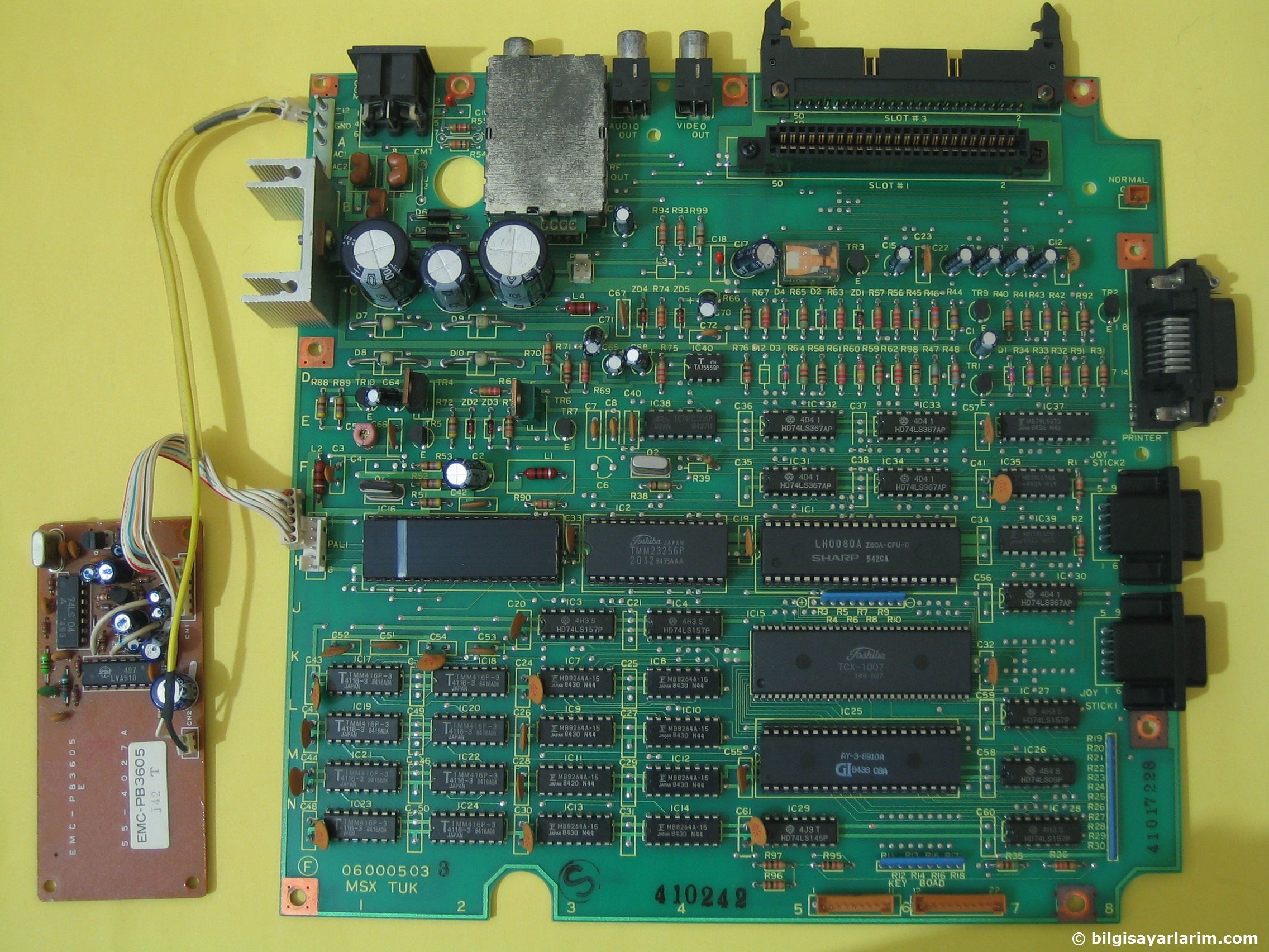
On the back there is a so called 50 pin dual row expansion connector, which is in fact a cartridge slot.
I know of Toshiba HX-10, Sanyo MPC100, Spectravideo SVI.728, Deawoo CPC-200, Goldstar FC200 to have such a connector, which can be made into a second cartridge slot.
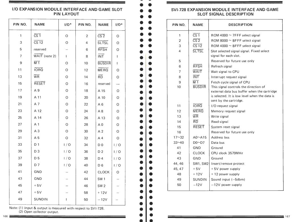
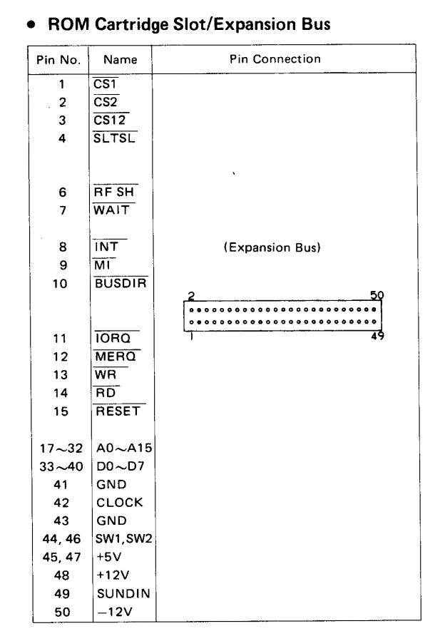
As you can see (page extracted from the SVI.728 service manual) the pin setting is identical.
Just to be sure, to know what is on what pin, measure e.g. the voltages on the connector! Pin 50 is -12V, pin 48 +12V , 45 and 47 +5V, 41 and 43 is ground. Do this also on the MSX Cartridge connector so you really know what is up or down or left or right!
Warning: Inserting a cartridge in the wrong way may kill your computer, having up and down row mixed up also. SO MEASURE! And make it clear how to insert a cartridge, by physically inserting an obstruction to prevent that. See the example here after for such a simple but effective construction
There after it is not too difficult to create a cable to make a second cartridge slot. You will need a 50 pin dual row connector to fit in the rear of the computer and a 50 pin MSX compatible cartridge slot connector.
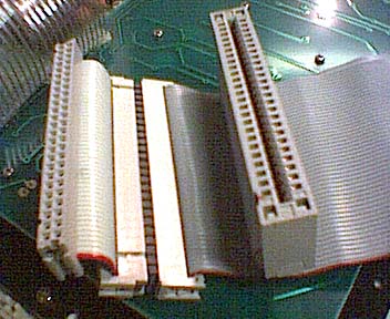
If you are lucky you can reuse an old SCSI cable and get a crimp on cartridge connector.
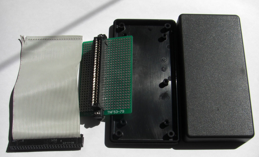
If the cartridge connector is the PCB type, you might use an experimenters print and solder the wires.
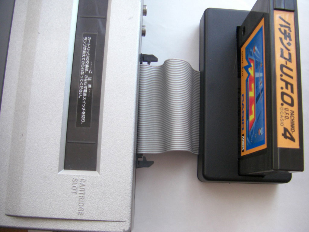
Here is a nice example by GDX, first published on MSXVillage in french. Translation errors are mine!
What you need :
1 male 50-pin connector. It is the same connector as the old SCSI hard drives.
1 50P ribbon cable 15 to 20 cm long (SCSI type)
1 MSX SLOT connector (“Card Edge Connectors 50 pin”)
A plate with holes (“Veroboard”).
1 housing to fix the plate. (a box found in electronics stores)
1 small round file.
1 small flat file.
1 hand drill.
1 cutter and good scissors.
1 soldering iron 25 ~ 40W.
Solder.
1 wire stripper.
vice. (Not required if you are recovering a SCSI cable)
How to make:
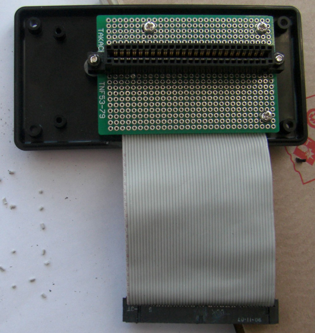
1 / Solder the SLOT MSX connector onto the hole plate. Place it where you think it is most appropriate for the case you have.
2 / Drill the mounting holes of the plate in advance. Caution, allow the cable to pass through.
3 / Crimp the connector on the cable cable with the vice. Be careful that the cable is in the correct position. Avoid putting it off.
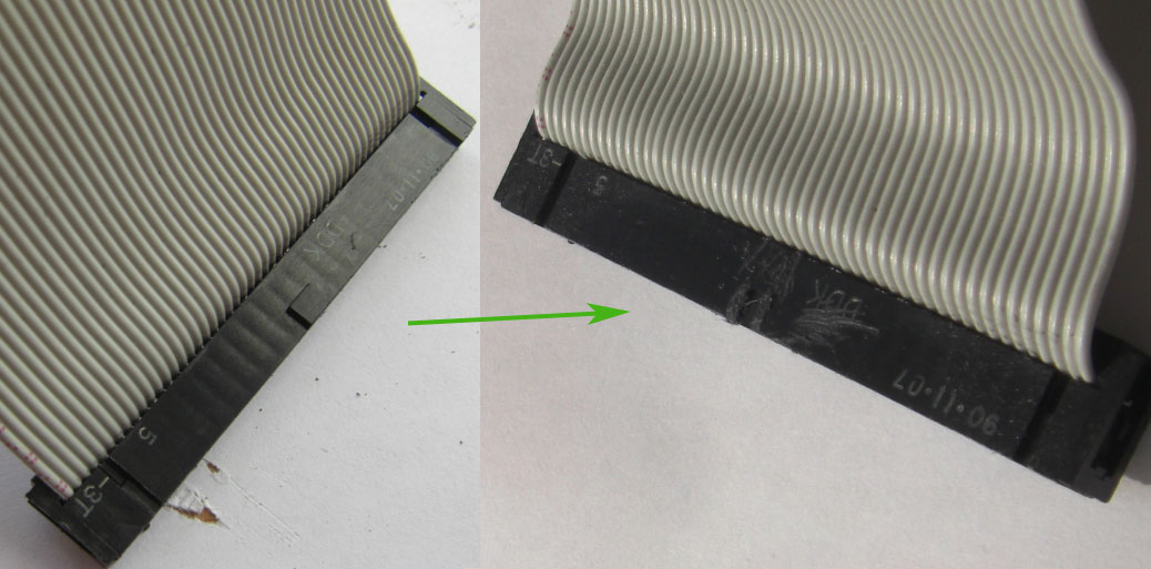
I did not have to do this manipulation. Because I used a piece of SCSI recovery cable. This cable has only one key in the middle instead of two as on the extension bus connector, so I had to file it so that it could fit into the connector of the bus.
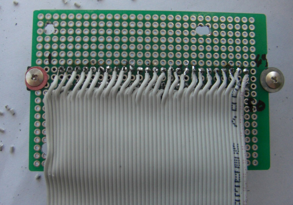
4 / Separate each wire on the other end about 1 cm with a cutter and cut all even cables (2, 4, 6, ~, 50) 6 mm with scissors.
5 / Strip each wire to 1 mm, no more because the insulation shrinks when it is heated, then tin each wire and solder them one by one to the MSX connector starting with the even pins. Check each solderpoint (with a magnifying glass if necessary) for even wires before soldering the odd wires. Check each solder joint of the odd wires as well.
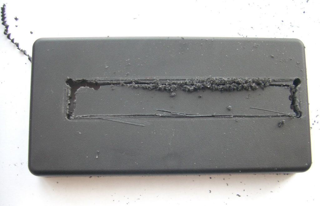
6 / To drill the SLOT slot of the cartridge into the housing, attach the plate into the housing, put an MSX cartridge into the SLOT and make measurements. I first used a cutter but being ineffective (it’s seen in the photo), so I used a hand drill and a small round file. With that, it’s done quickly. The small file file serves for finish. A tip, first make a slot too small for the cartridge then adjust the size with the file flat until the cartridge fits well.
7 / The slot for the cable is easily inserted with the flat file.
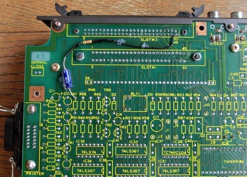
On the Toshiba HX-10 the expansion cartridge will be slot 3, It is so indicated on the PCB as seen in the next photo.
On some computers like the HX10 the SOUNDIN (pin 49) seems not connected. You can fix that, find the audio combine inout point of the audio amplifier on the PCB by following the resistor/capacitor line from the cartridge connector to pin 49 on the cartridge slot. A bit complicated without circuit diagram to explain, it isusually a resistor and a capacitor in series.
Here is how GDX did it on a HX-10.
Pin 49 of the SLOT-3 is connected to a 10 KΩ resistor which is connected to the (-) side of a 10 μF capacitor. The (+) side goes to the amplifier. Now the Slot is 100% functional.

