FDD repair
Original japanese page: http://www.h6.dion.ne.jp/~levin_tr/index.htm
When it reaches the point where error occurs in FDD of MSX, below-mentioned item probably will be verified first.
If it does not solve with the below-mentioned disposal, it is thought that exchange of drive itself is needed. As for exchange please go on self responsibility.
| Region | Verification item | There is a possibility FDD reviving with the below-mentioned disposal. | |
| @ | Connector and wiring. | Coming out of connector and contact failure and broken wire of wiring. | The connector it does again to put, cleaning near the connector (removal of the dust), according to, the respective circumstance such as use of the contact point revival medicine and restoration of the broken wire part appropriately it deals with. |
| A | Head of drive. | Soiling of head. | Because with naked eye it is not understood, the cleaning liquid (for [hetsuto] of the tape deck) being able to soak in the cotton stick, it cleans the head. (With the wet floppy type cleaner it seems that is the soiling which does not fall. ) It reads and the time strange noise does, on the disk surface of the floppy can designate the scar as circular condition. |
| B | FDD belt. | State of FDD belt. | With drive of belt system, the rubber belt is used in order to convey the revolution of the motor. This belt extending with the lapse of the number of years, there are times when it loosens, deteriorates and can and/or they have become not be able to transmit revolution. In this case the belt is exchanged to the new item. |
Type turn of the belt of FDD of MSX.
Inquiring stock to service center of the manufacturer, if there was a stock, the major electric store (with the lightning warehouse it was all right. ) With it makes do to obtain, it seems that. (In only cost of the belt makes do to obtain the FDD belt of Panasonic, could. (2003 May) it is grateful thing. ) Type turn zero one of the belts of Panasonic the fact that it is not enough was corrected. (2006/01/06) It does, it is increase it is.
| Item name | Type turn | Manufacturer | Corresponding type |
| FDD belt | DFWV75C0009 | Panasonic | FS-A1F/FX/WX/WSX/ST/GT (MSX2/MSX2+/MSXturboR) |
| [hiraberuto] | 9-994-678-01 | SONY | HB-F1XDmk2, HB-F1XDJ and HB-F1XV |
About the FDD exchange of MSX. (34PIN or 26PIN or 24PIN)
For DOS/V FDD which presently can be procured with the new item (34PIN) there is no READY signal, connects 34PIN and does not operate normally. With saying, if it processes the cable, you can use. (Connecting that way, the type which you can use (FS-4600F? There is a unconfirmed report that) it is. )
| Whole | ||||||
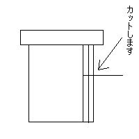
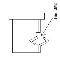
| When for DOS/V FDD (34PIN) conversion it does. (Basic, the cable just is processed. ) < Common item > Because, there is no READY signal in one for DOS/V FDD, it copes with the method of connecting” GND” to” READY”. But, with this method there is a disk and nothing dies and does not relate, unless when accessing because always drive becomes READY state, the disk has entered, it becomes error and/or drives recklessly. (Cancellation method: You insert the disk always, or attach the switch between” READY” and” GND,” when using just, you turn to ON. It seems that also higher-level method is, but here it does not touch. ) 34PIN SONY MSX of system The number of pins being the same, because also position of the signal generally is the same, when” Drive Select 1” is connected,”” GND” is connected to READY”, you can use. When you can understand with diagram under, it is very grateful, is. So, as for job please go on self responsibility. With this failing, responsibility it cannot have.
26PIN MSX of or 24PIN>Panasonic type |
||||||
| FS-A1F (26PIN) | ||||||
| In DriveSelect0””” DriveSelect1” and” Motor ON”” MotorEnable1” and 5V (3,5,7) which red of power source, 1 of N.C yellow of power source, other things connected the line of the same name, did not connect N.C other than power source, but it seems that is not problem. You think that the person who used FDD whose position of the connector of 34PIN and power source is not the same is good. Because (D353M3D of MITSUMI which this time is used (black), position is the same, wiring near the connector was packed and said. ) ”” GND” was connected to Ready”, but if the floppy has entered when starting, it seems that is not problem. When (there is no disk is, it stops in the blue picture. In addition, the disk having entered, it seems that remains makes ROM START when the access lamp been attached. ) As for job of the connecting changing, patience needs well enough. (3 hours it was required. But), if one time it connects and changes, because with just exchange of drive is completed from the next, as for the value which is done you think that greatly it is. Forever in order to use MSX, it is the work of being necessary. |
||||||
| HBD-20W (34PIN) | ||||||
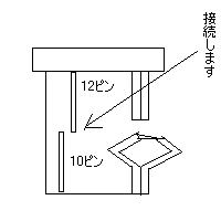
| YD-702D-6639D (the READY signal to be) with the installation, 10 (Drive Select 1) 6639D of MSX 12 (Drive Select 1) it connects and just changes and, it can use without problem. Case of DOS/V FDD, if 33 (GND) with 34 (Disk Change) it connects in addition to that, when the Ready signal is input on MSX side, because you recognize, it is the expectation which reaches the point where you can use. Because for DOS/V and as for YD-702D-6639D, height is not enough in comparison with genuine FDD, it is not agreeable to the height of the window that way. When the hexagonal spacer for the motherboard of DOS/V is used, it becomes exactly blade height. Now the window is not processed and also the [te] becomes good. |
||||||
| FDD, YD-702D-6639D of the YE-DATA corporation can output the READY signal due to the setting of the jumper. Because (at 2003/06 point in time, (it seems that is the branch office in entire country, each one please try inquiring. ) With by way of the agency which is said 6000 Yen with it was available (classified by tax). At the major electric store it seemed that cannot be obtained. ) If it is the exchange of 34PIN, position of the signal almost is the same. ” Drive Select 1” of the cable the fellow just is connected. (Connecting that way, you can use, but allotment of drive C, becomes D drive. ) I have used setting of the jumper of YD-702D-6639D, T2, DS1, IF and RY short. As for the details of YD-702D-6639D, please view PDF which is the YE-DATA corporation home page. In addition, YD-702J-6637J of 26PIN (there to be a READY signal) with slim FDD you say (half scantness of normal drive) it seems that is. However, because as for this, pin assign does not agree even 26PIN, being able to meet, perhaps the necessity to select it is not. *YD-702D-6639D not only the MSX user, is thought that it is the floppy drive which is very effective to the FM-TOWNS user. |
||||||
| For FM-TOWNS FDD (34PIN ready signal possession) | ||||||
| If the SONY affiliation can procure one for FM-TOWNS FDD of the all-inclusive dynamic item, it seems that can use with just exchange. As for panasonic system, main point connecting changing. |
The pin assign of FDD.
In the below-mentioned chart * option setting (with jumper pin setting possibility. ) The odd number pin of 34PIN is GND. Those which have the parenthesis with the number of PIN the case of conversion, are something which is possible to be not yet connection. Name differs, but you must connect, the part, it connects and must change the part made the color of the cell the same.
| MSX (34PIN) | For AT compatible machine (34PIN) |
YD-702D-6639D (34PIN) |
|||||
| 1 | GND | NC | 2 | High Density | 2 | Mode Select /Disk Change* /High Density* |
2 |
| 3 | GND | NC | 4 | NC | 4 | High Density* | 4 |
| 5 | GND | NC | 6 | NC | 6 | NC | 6 |
| 7 | GND | INDEX | 8 | INDEX | 8 | INDEX | 8 |
| 9 | GND | Drive Select 1 | 10 | Motor Enable 0 | (10) | Drive Select 0 | (10) |
| 11 | GND | Drive Select 2 | (12) | Drive Select 1 | 12 | Drive Select 1* | 12 |
| 13 | GND | Drive Select 3 | (14) | Drive Select 0 | 14 | NC | 14 |
| 15 | GND | Motor ON | 16 | Motor Enable 1 | 16 | Motor ON | 16 |
| 17 | GND | Direction | 18 | Direction | 18 | Direction Select | 18 |
| 19 | GND | Step Pulse | 20 | Step Pulse | 20 | Step | 20 |
| 21 | GND | Write Data | 22 | Write Data | 22 | Write Data | 22 |
| 23 | GND | Write Enable | 24 | Write Enable | 24 | Write Gate | 24 |
| 25 | GND | Track 0 | 26 | Track 0 | 26 | Track 00 | 26 |
| 27 | GND | Write Protect | 28 | Write Protect | 28 | Write Protect | 28 |
| 29 | GND | Read Data | 30 | Read Data | 30 | Read Data | 30 |
| 31 | GND | Side 1 Select | 32 | Select Head | 32 | Side 1 Select | 32 |
| 33 | GND | Ready | 34 | Disk Change | (34) | Ready/Disk Change* | 34 |
| FS-A1F (26PIN) |
For AT compatible machine (34PIN) |
YD-702J 6637J (26PIN) |
|||||||
| 1 | NC | Ready | 2 | High Density | (2) | 1 | +5V | INDEX | 2 |
| 3 | 5V | INDEX | 4 | NC | 4 | 3 | +5V | Drive Select 0 | 4 |
| 5 | 5V | Drive Select 0 | 6 | NC | 6 | 5 | +5V | Disk Change | (6) |
| 7 | 5V | NC | 8 | INDEX | 8 | 7 | NC | Ready | 8 |
| 9 | NC | Side 1 Select | 10 | Motor Enable 0 | (10) | (9) | High Density | Motor ON | 10 |
| 11 | NC | Motor ON | 12 | Drive Select 1 | 12 | 11 | NC | Direction | 12 |
| 13 | NC | Direction | 14 | Drive Select 0 | (14) | (13) | Mode Select | Step | 14 |
| 15 | NC | Step | 16 | Motor Enable 1 | 16 | (15) | GND | Write Data | 16 |
| 17 | GND | Write Data | 18 | Direction | 18 | 17 | GND | Write Gate | 18 |
| 19 | GND | Write Gate | 20 | Step Pulse | 20 | 19 | GND | Track 00 | 20 |
| 21 | GND | Track 00 | 22 | Write Data | 22 | 21 | GND | Write Protect | 22 |
| 23 | GND | Write Protect | 24 | Write Enable | 24 | 23 | GND | Read Data | 24 |
| 25 | GND | Read Data | 26 | Track 0 | 26 | 25 | GND | Side 1 Select | 26 |
| Write Protect | 28 | ||||||||
| Read Data | 30 | ||||||||
| Select Head | 32 | ||||||||
| Disk Change | (34) |
| FS-A1WX/ WSX/ST/GT (24PIN) |
For AT compatible machine (34PIN) |
YD-702J 6637J (26PIN) |
|||||||
| 1 | +5V | +5V | 2 | High Density | (2) | 1 | +5V | INDEX | 2 |
| 3 | NC | +5V | 4 | NC | 4 | 3 | +5V | Drive Select 0 | 4 |
| 5 | +5V | Ready | 6 | NC | 6 | 5 | +5V | Disk Change | 6 |
| 7 | GND | GND | 8 | INDEX | 8 | 7 | NC | Ready | 8 |
| 9 | Side 1 Select | GND | 10 | Motor Enable 0 | (10) | (9) | High Density | Motor ON | 10 |
| 11 | Read Data | Write Protect | 12 | Drive Select 1 | 12 | 11 | NC | Direction | 12 |
| 13 | Track 00 | Write Gate | 14 | Drive Select 0 | (14) | (13) | Mode Select | Step | 14 |
| 15 | GND | Write Data | 16 | Motor Enable 1 | 16 | 15 | GND | Write Data | 16 |
| 17 | GND | Step | 18 | Direction | 18 | 17 | GND | Write Gate | 18 |
| 19 | Direction Select | Motor ON | 20 | Step Pulse | 20 | 19 | GND | Track 00 | 20 |
| 21 | NC | Drive Select | 22 | Write Data | 22 | 21 | GND | Write Protect | 22 |
| 23 | INDEX | Disk Change | 24 | Write Enable | 24 | 23 | GND | Read Data | 24 |
| Track 0 | 26 | 25 | GND | Side 1 Select | 26 | ||||
| Write Protect | 28 | ||||||||
| Read Data | 30 | ||||||||
| Select Head | 32 | ||||||||
| Disk Change | (34) |
34PIN connector. (The cable has lined up, from the left like the 1→34. )
| On | ||||||||||||||||
| 2 | 4 | 6 | 8 | 10 | 12 | 14 | 16 | 18 | 20 | 22 | 24 | 26 | 28 | 30 | 32 | 34 |
| 1 | 3 | 5 | 7 | 9 | 11 | 13 | 15 | 17 | 19 | 21 | 23 | 25 | 27 | 29 | 31 | 33 |
Direct voltage source connector of FDD & pin arrangement. (From YD-702D product specification. )
| On (above) | ||||
| Pin numbering | 4 (yellow) yellow | 3 (black) black | 2 (black) black | 1 (red) red |
| Name | NO CONNECTION | +5V RETURN | +5V RETURN | +5V DC |
