Second slot HX10, MPC100, SVI.728, CPC-200, FC-200

ome MSX-1 computers seem to have only one cartridge slot, on top.

On the back there is a so called 50 pin dual row expansion connector, which is in fact a cartridge slot.

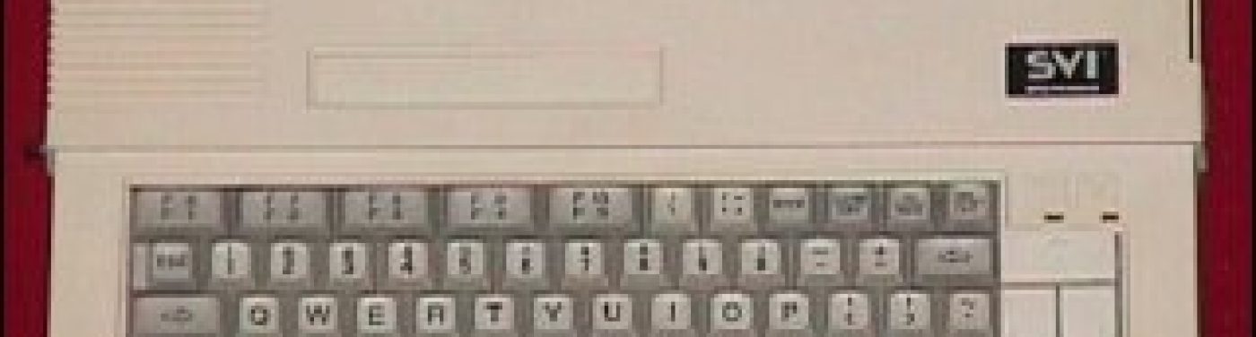
I know of Toshiba HX-10, Sanyo MPC100, Spectravideo SVI.728,  Deawoo CPC-200, Goldstar FC200 to have such a connector, which can be made into  a second cartridge slot.

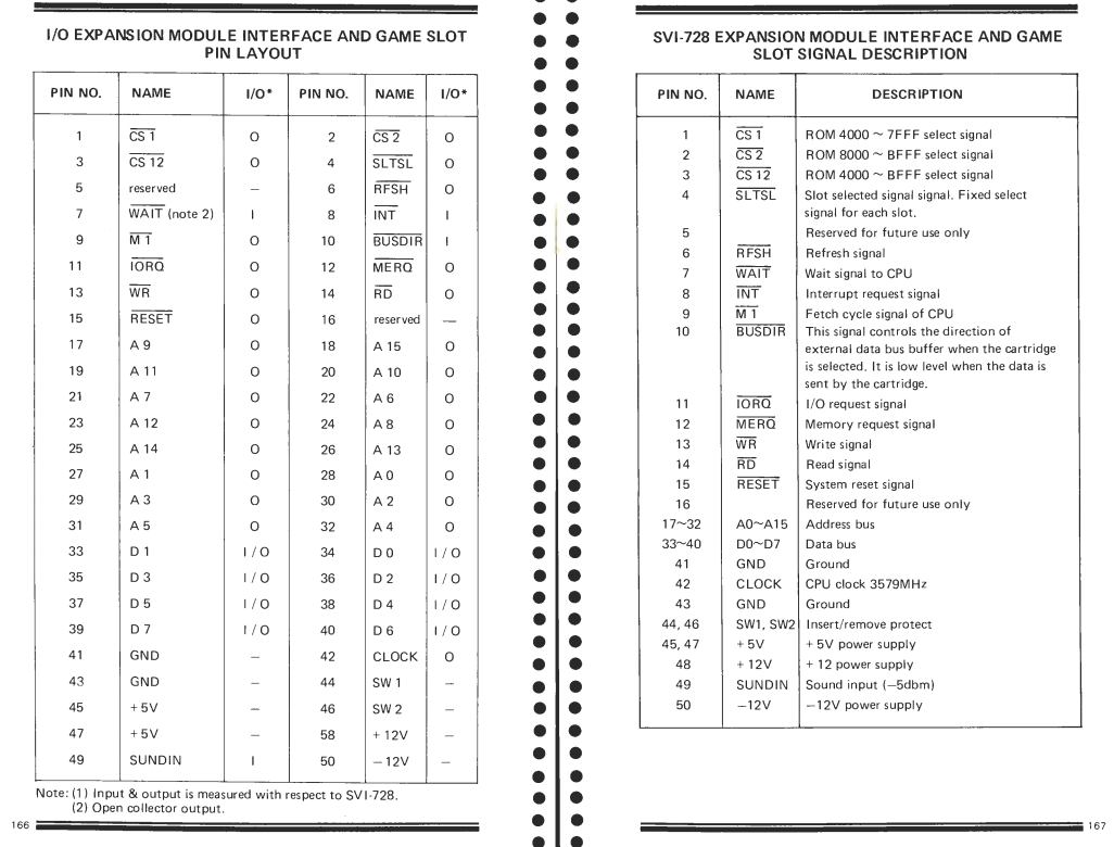
As you can see (page extracted from the SVI.728 service manual) the pin setting is identical.

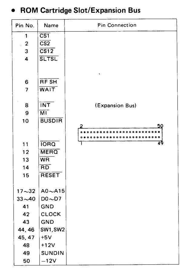
From the Sanyo MPC100 manual.

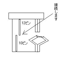
Just to be sure, to know what is on what pin, measure e.g. the voltages on the connector! Pin 50 is -12V, pin 48 +12V , 45 and 47 +5V, 41 and 43 is ground. Do this also on the MSX Cartridge connector so you really know what is up or down or left or right!

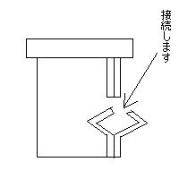
Warning: Inserting a cartridge in the wrong way may kill your computer, having up and down row mixed up also. SO MEASURE!  And make it clear how to insert a cartridge, by physically inserting an obstruction to prevent that. See the example here after for such a simple but effective  construction

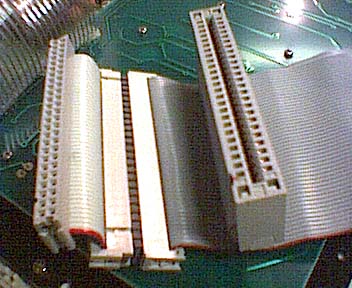
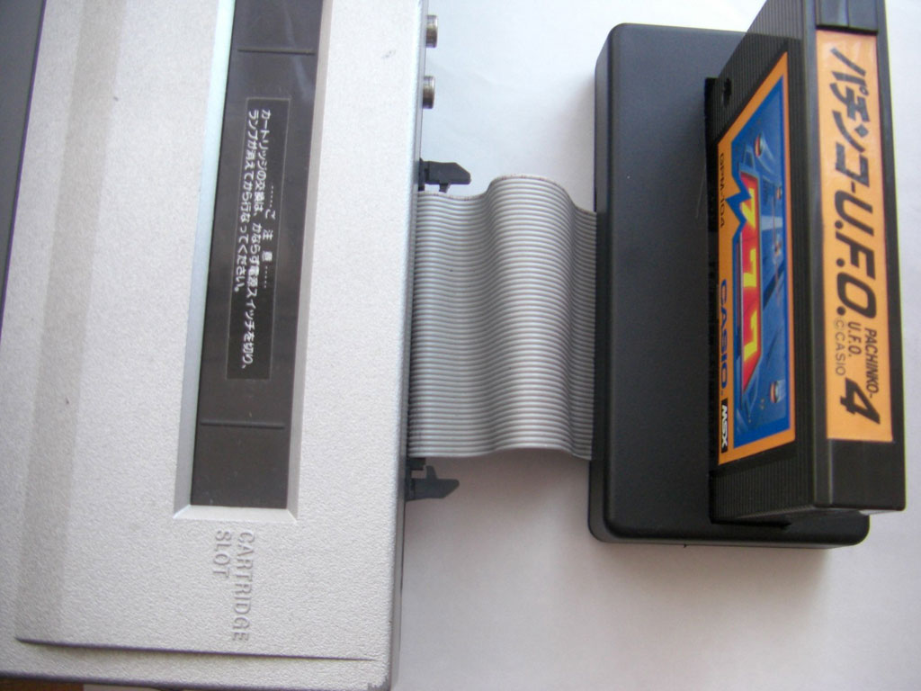
There after it is not too difficult to create a cable to make a second cartridge slot. You will need a 50 pin dual row connector to fit in the rear of the computer and a 50 pin MSX compatible cartridge slot connector.
If you are lucky you can reuse an old SCSI cable and get a crimp on cartridge connector.

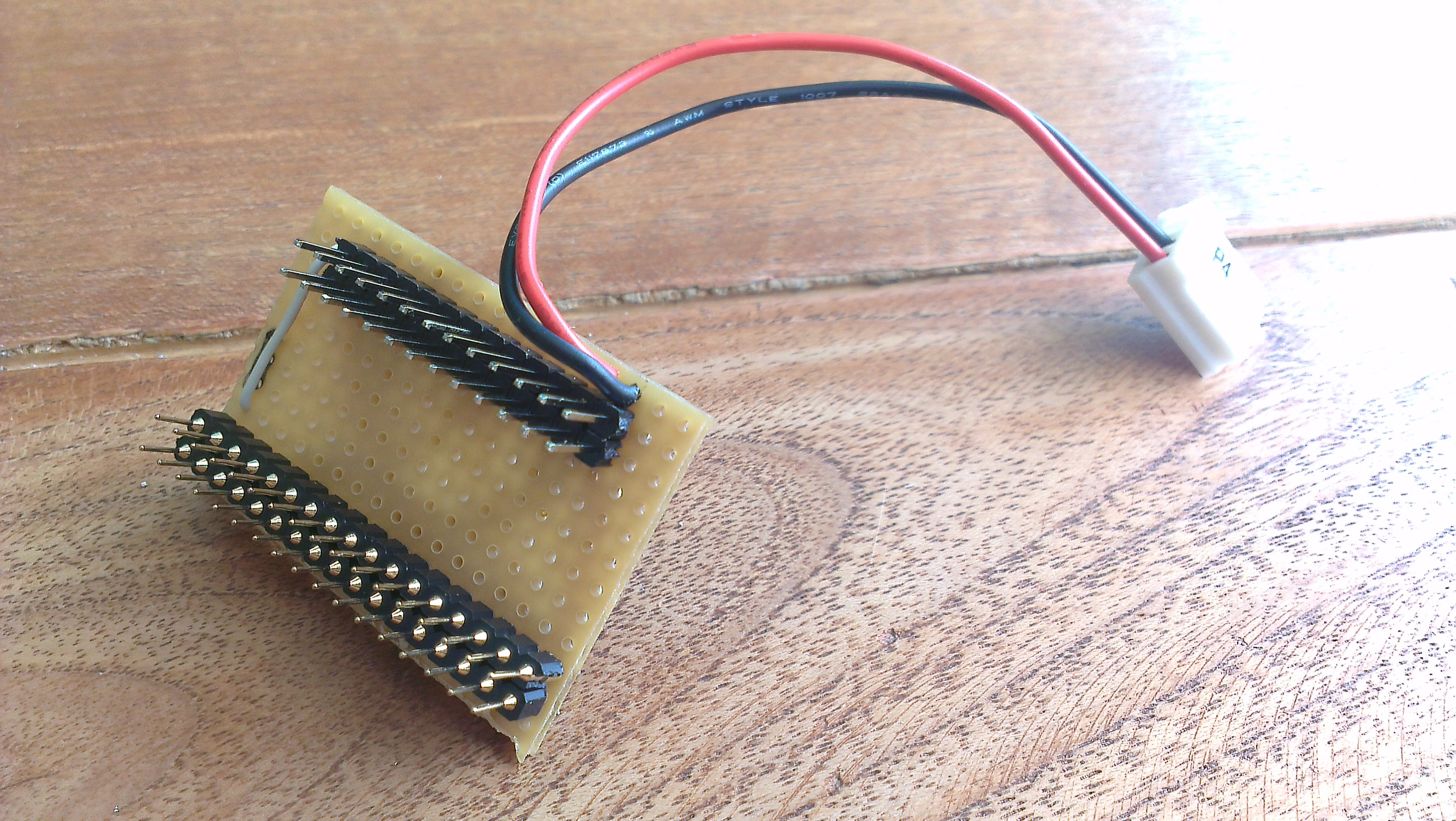
If the cartridge connector is the PCB type, you might use an experimenters print and solder the wires.

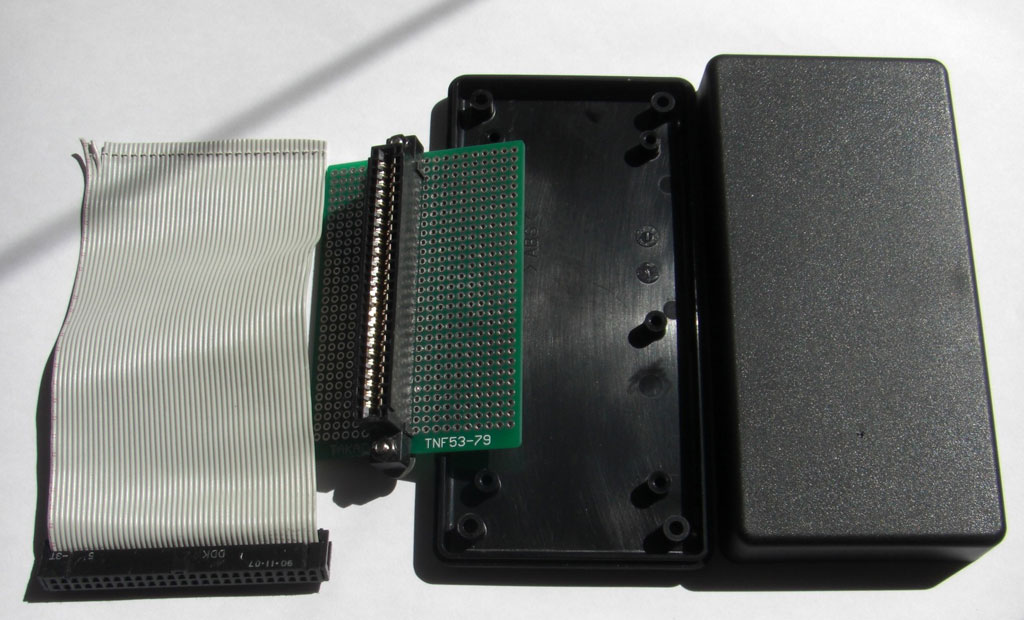
Here is a nice example by GDX, first published on MSXVillage in french. Translation errors are mine!

What you need :

1 male 50-pin connector. It is the same connector as the old SCSI hard drives.
1 50P ribbon cable 15 to 20 cm long (SCSI type)
1 MSX SLOT connector (“Card Edge Connectors 50 pin”)
A plate with holes (“Veroboard”).
1 housing to fix the plate. (a box found in electronics stores)

Necessary tools :

1 small round file.
1 small flat file.
1 hand drill.
1 cutter and good scissors.
1 soldering iron 25 ~ 40W.
Solder.
1 wire stripper.
vice. (Not required if you are recovering a SCSI cable)

How to make:

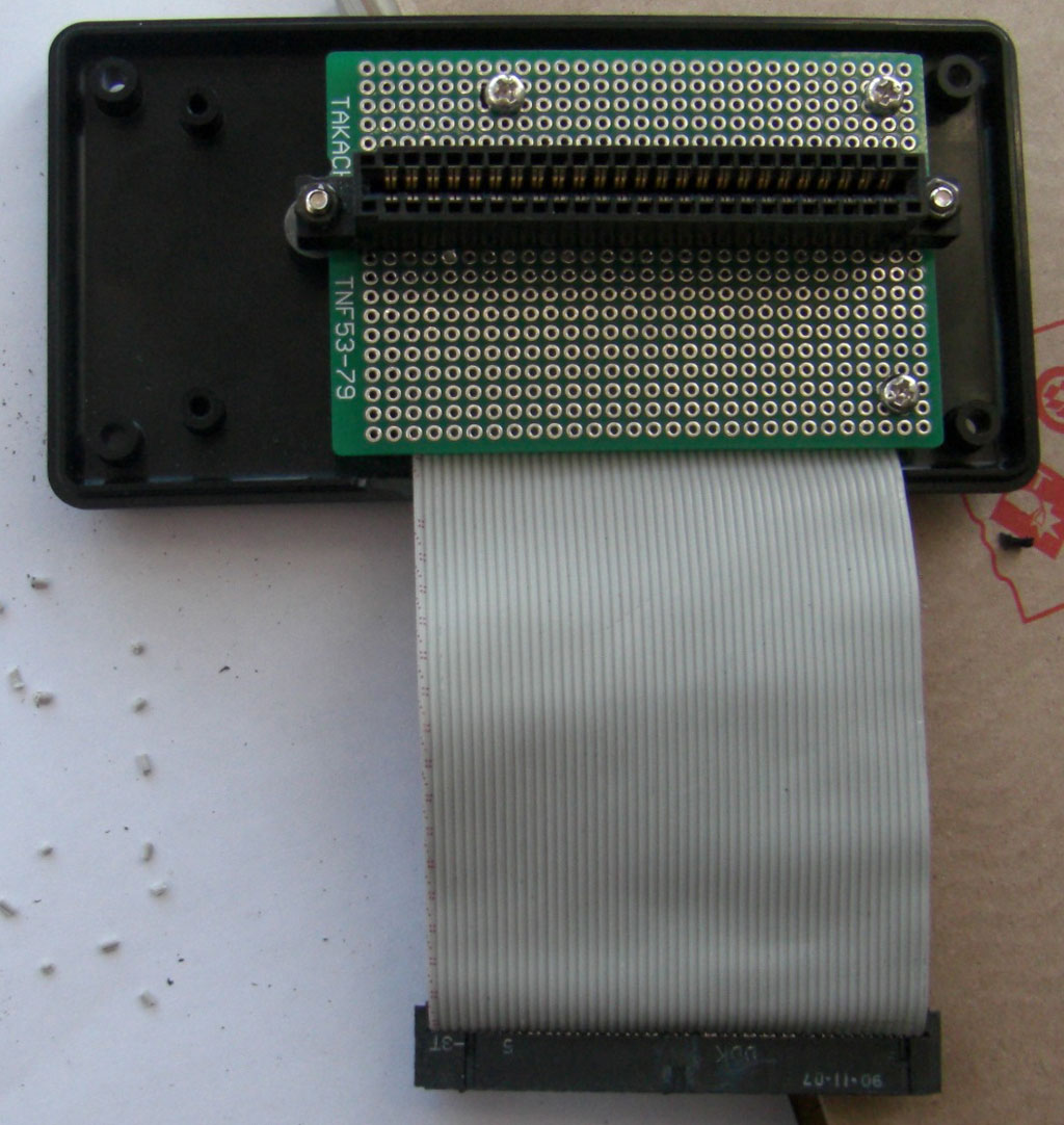
1 / Solder the SLOT MSX connector onto the hole plate. Place it where you think it is most appropriate for the case you have.

2 / Drill the mounting holes of the plate in advance. Caution, allow the cable to pass through.

3 / Crimp the connector on the cable cable with the vice. Be careful that the cable is in the correct position. Avoid putting it off.
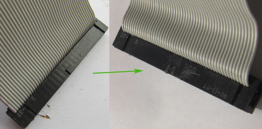
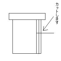
I did not have to do this manipulation. Because I used a piece of SCSI recovery cable. This cable has only one key in the middle instead of two as on the extension bus connector, so I had to file it so that it could fit into the connector of the bus.

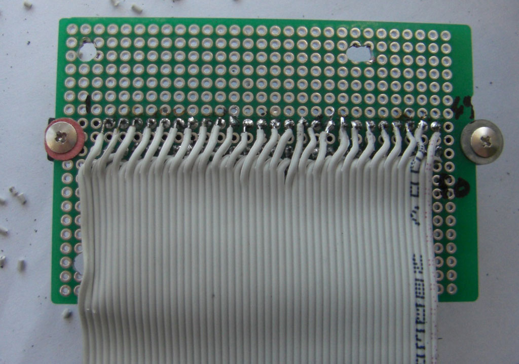
4 / Separate each wire on the other end about 1 cm with a cutter and cut all even cables (2, 4, 6, ~, 50) 6 mm with scissors.

5 / Strip each wire to 1 mm, no more because the insulation shrinks when it is heated, then tin each wire and solder them one by one to the MSX connector starting with the even pins. Check each solderpoint (with a magnifying glass if necessary) for even wires before soldering the odd wires. Check each solder joint of the odd wires as well.

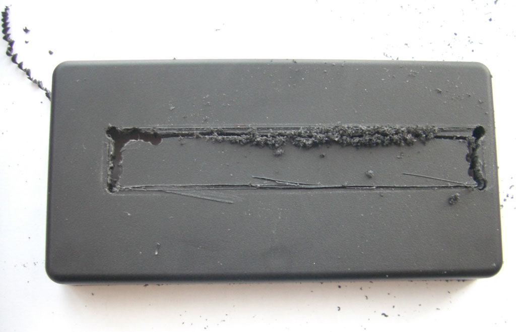
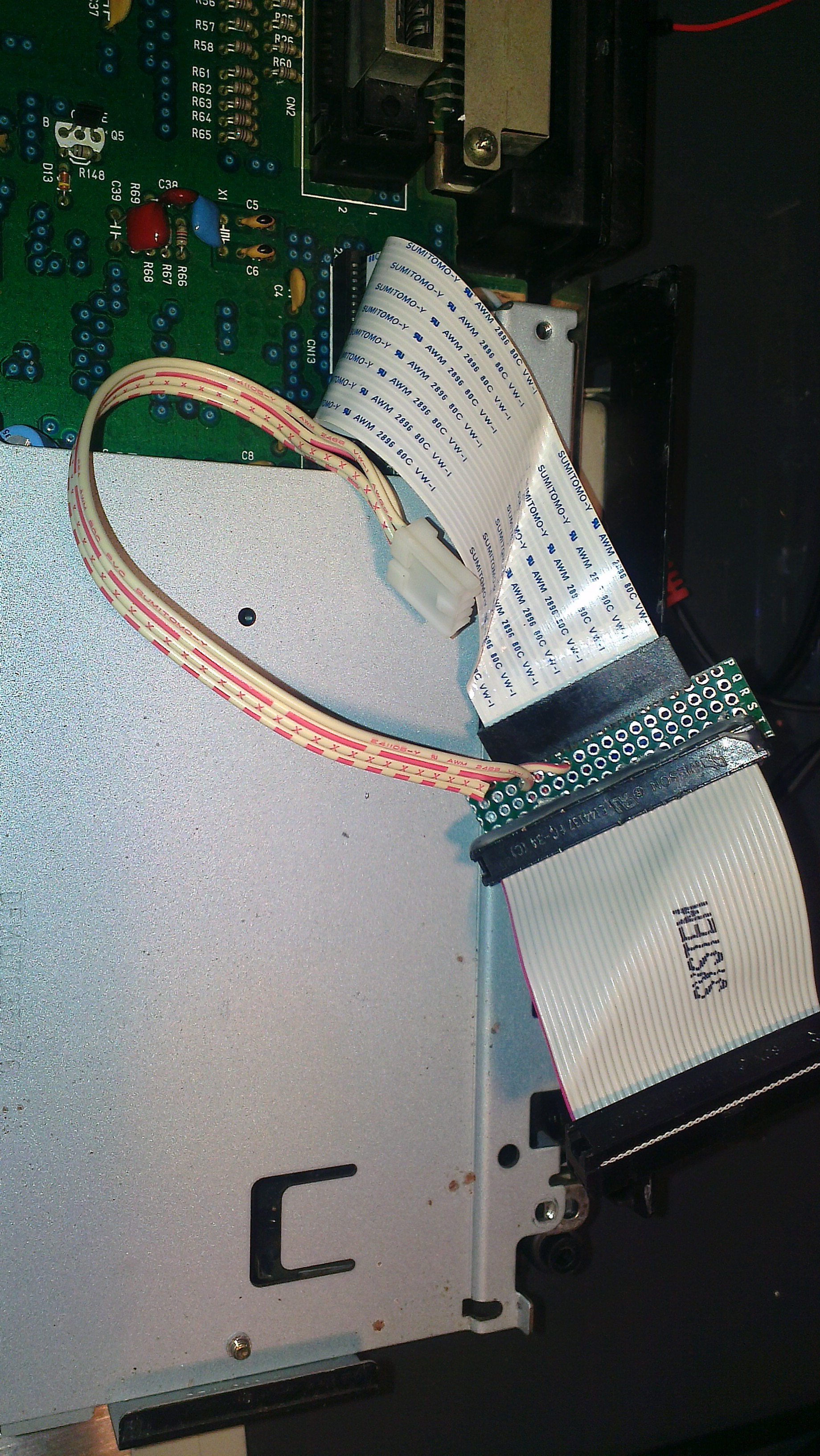
6 / To drill the SLOT slot of the cartridge into the housing, attach the plate into the housing, put an MSX cartridge into the SLOT and make measurements. I first used a cutter but being ineffective (it’s seen in the photo), so I used a hand drill and a small round file. With that, it’s done quickly. The small file file serves for finish. A tip, first make a slot too small for the cartridge then adjust the size with the file flat until the cartridge fits well.

7 / The slot for the cable is easily inserted with the flat file.

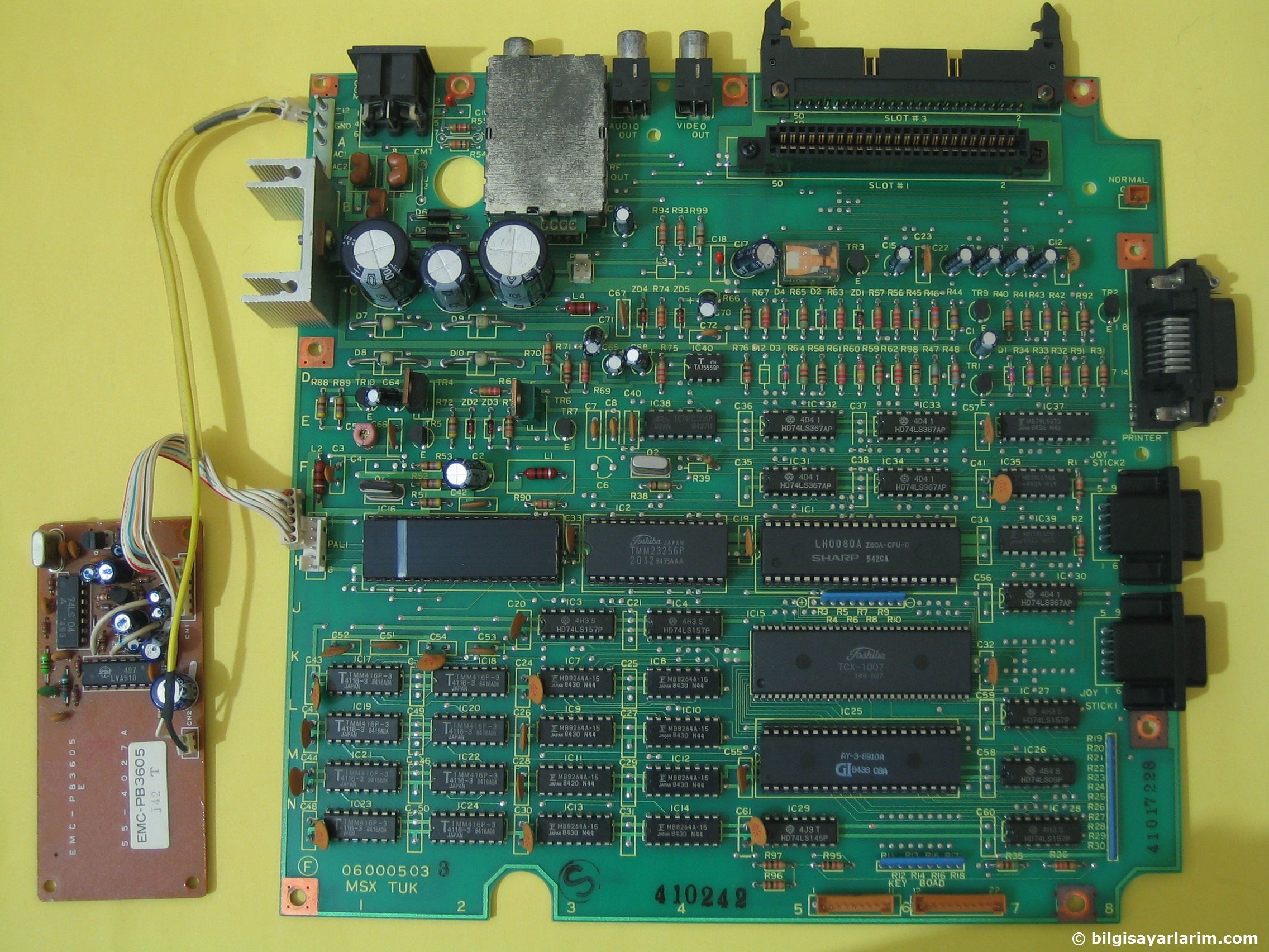
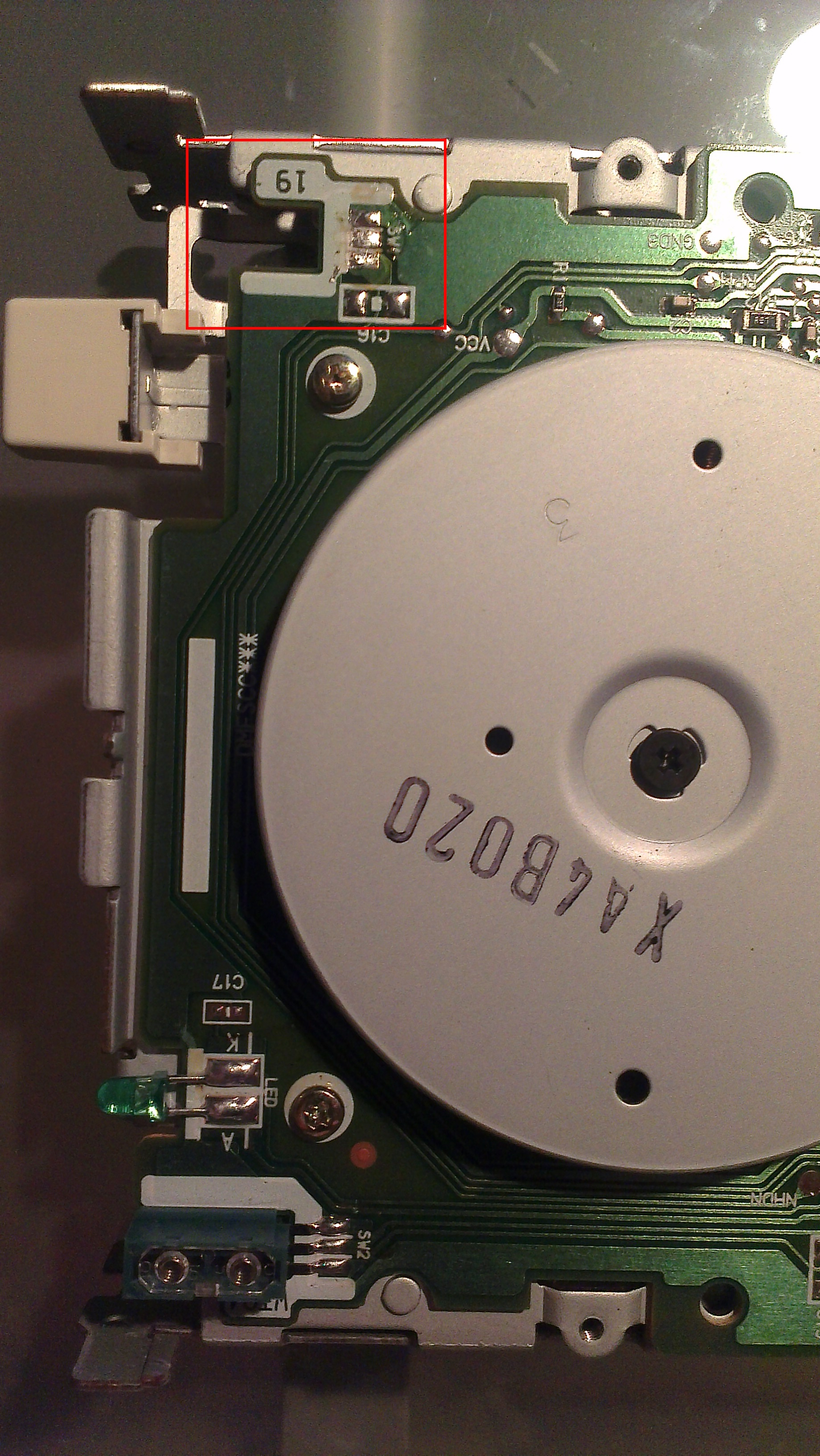
On the Toshiba HX-10 the expansion cartridge will be slot 3, It is so indicated on the PCB as seen in the next photo.


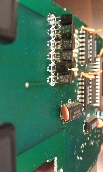
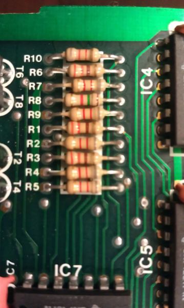
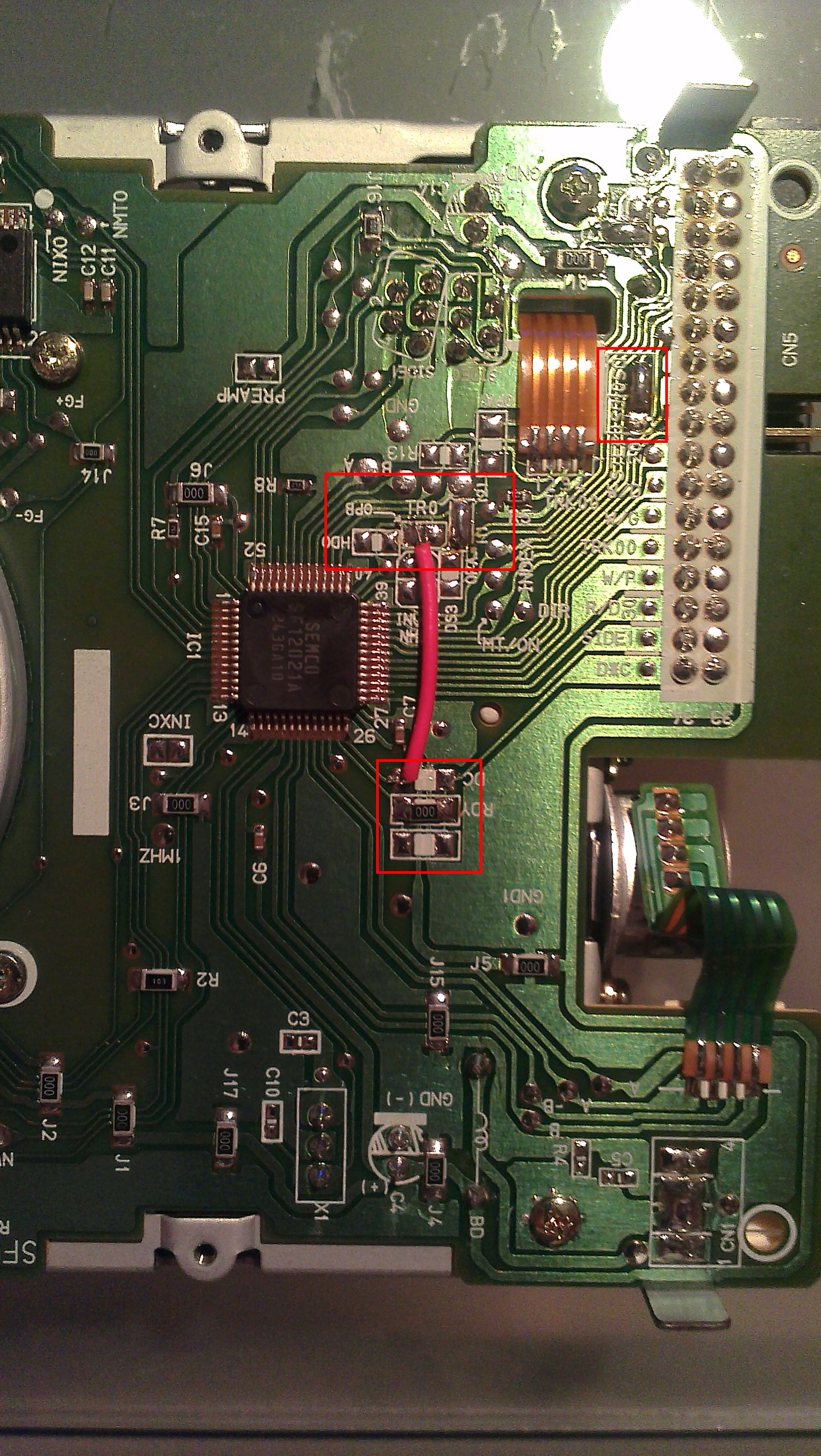
On some computers like the HX10 the SOUNDIN (pin 49) seems not connected. You can fix that, find the audio combine inout point of the audio amplifier on the PCB  by following the resistor/capacitor line from the cartridge connector to pin 49 on the cartridge slot. A bit complicated without circuit diagram to explain, it isusually a resistor and a capacitor in series.

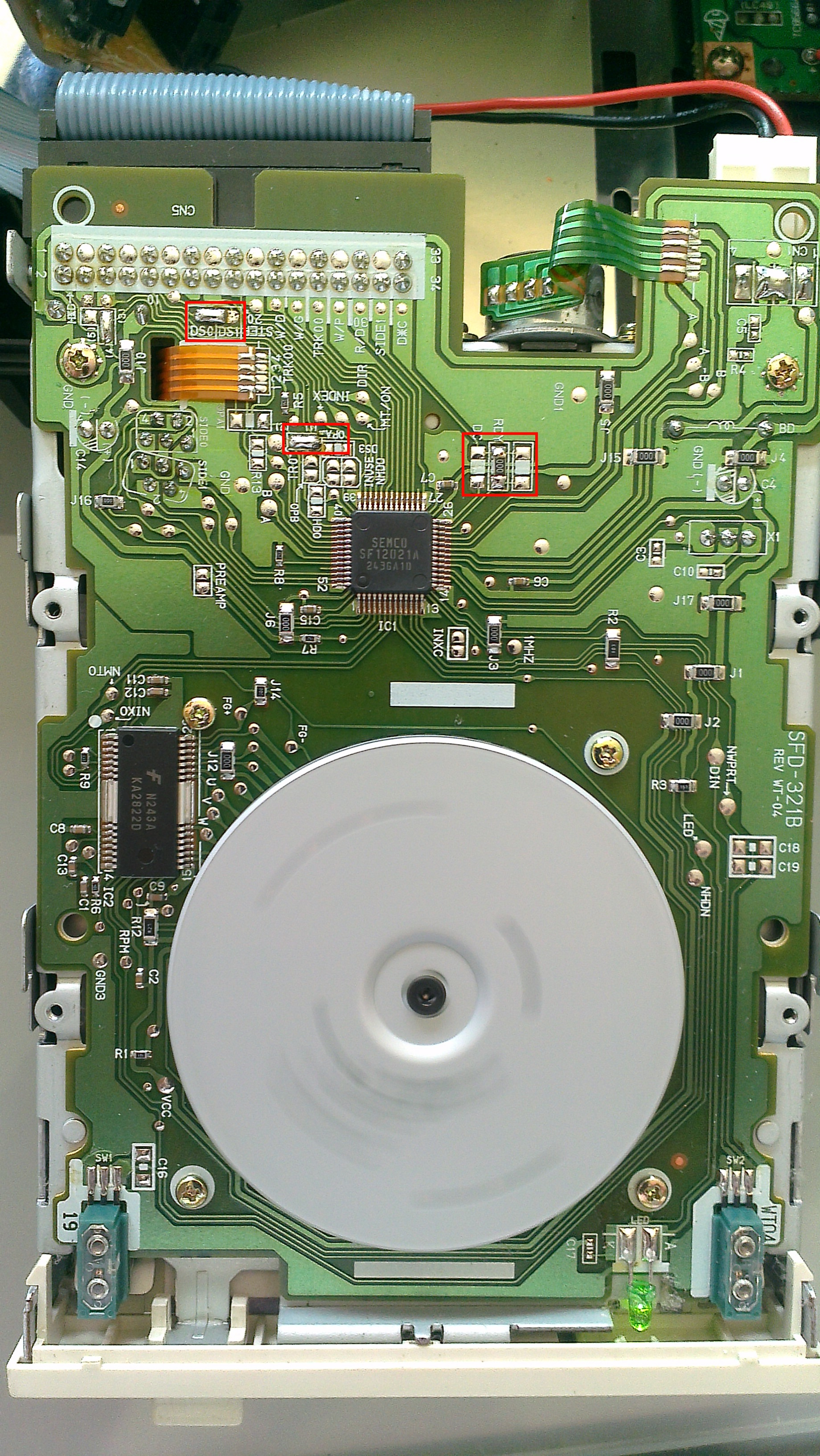
Here is how GDX did it on a HX-10.

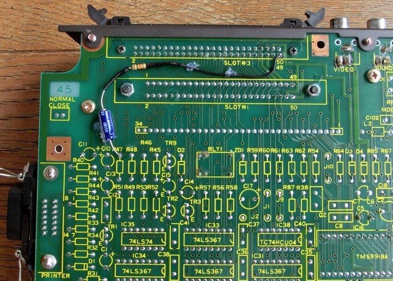
Pin 49 of the SLOT-3 is connected to a 10 KΩ resistor which is connected to the (-) side of a 10 μF capacitor. The (+) side goes to the amplifier. Now the Slot is 100% functional.

post

SVI Spectravideo robot arm

Svi 2000
Svi 2000
Svi 2000
See also the DIY Robotarm catridge page.
Spectravideo SVI 2000 Robotarm userguide (including Rogo the programming language)

Original Rogo ROM

MSX 2 version of ROGO for the SVI.2000 Spectravideo robot, thanks to Jipe!

MSX 2 adapted ROGO ROM

NYYRIKKI made another version based on this modified version. Changes:
– ROM will now pass selftest correctly (if burned to EPROM without problems)
– ROGO does not autoboot, but can be started from BASIC with CALL ROGO command or by holding “R”-key down during boot.

MSX 2 no autoboot ROGO ROM


turboR PC disk drive


Replace a MSX turboR Diskdrive with a PC Drive.

Instruction designed and written by Erik Luppes (luppie), original here, reproduction kindly permitted by Erik.

This instruction shows how to connect a Samsung SFD-321B FDD to a :

Panasonic FS-A1FX
Panasonic FS-A1WX
Panasonic FS-A1WSX
Panasonic FS-A1ST
Panasonic FS-A1GT

On the Internet I found a couple of instructions on howto connect a PC drive to a Panasonic MSX. In my opinion these instructions are to complex and/or not 100% compatible with the original diskdrive. (DiskChange via a switch to ground, extra TTL logic for the RDY signal)

This instruction works with older revisions of the Samsung SFD-321B.
Please make sure that the Samsung SFD-321B you use has a HD sensor (the newest revision of this drive does not have this sensor, causing no support for formatting 720kb DD disks)

To minimize the damage to the mainbord I chose to desolder the 24pin ZIF socket from the defect diskdrive. I’ve put this ZIF socket on a small prototype PCB together with a 17-pin header (even pins 2 -> 34) The odd pins are all connected to ground so not used.

On the small PCB the following connections are made:

Signal

24 pin ZIF

34 pin FDD

+5V

1

Power

Connector

RDY

6

34

GND

7

Power

Connector

Side Select

9

32

Read Data

11

30

Write Protect

12

28

Track 00

13

26

Write Gate

14

24

Write Data

16

22

Step

18

20

Direction Select

19

18

Motor On

20

16

Drive Select 0

22

10

Index

23

08

Disk Change

24

02

To make the Samsung SFD-321B 100% compatibel the following modifications need te be maded.

. Replace jumper DS1 to DS0 (To make it the A drive)
. Replace jumper DC to RDY (To put the RDY signal on pin 34)
. Solder a wire between DC and OPB (to put DC on pin 2)

Since the diskdrive has a HD Disk sensor, you need to put a piece of tape on the HD hole. To overcome this, it is possible to remove the HD sensor.

Now you’ve got a 100% compatible diskdrive, without modifications to your mainboard.

Panasonic PC drive


Replace a Panasonic FS-A1F Diskdrive with a PC Drive

Instruction designed and written by Erik Luppes (luppie), original here, reproduction kindly permitted by Erik.

This instruction shows how to connect a Samsung SFD-321B FDD to a Panasonic FS-A1F.

On the Internet I found a couple of instructions on howto connect a PC drive to a Panasonic MSX. In my opinion these instructions are too complex and/or not 100% compatible with the original diskdrive.

This instruction works with older revisions of the Samsung SFD-321B.
Please make sure that the Samsung SFD-321B you use has a HD sensor (the newest revision of this drive does not have this sensor, causing no support for formatting 720kb DD disks)

To minimize the damage to the mainbord I chose to make a small convertor on a small prototype PCB.

On the small PCB the following connections are made:

Signal

26 pin MSX

34 pin FDD

GND

01

Power

Connector

RDY

02

34

+5V

03

Power

Connector

Index

04

08

Drive Select 0

06

10

Motor ON

08

16

Side Select

10

32

Direction Select

14

18

Step

16

20

Write Data

18

22

Write Gate

20

24

Track 00

22

26

Write Protect

24

28

Read Data

26

30

To make the Samsung SFD-321B 100% compatible the following modifications need te be made.

Replace jumper DS1 to DS0 (To make it the A drive)
Replace jumper DC to RDY (To put the RDY signal on pin 34)
Put a jumper on OPA (this adds 720kb support)

Since the diskdrive has a HD Disk sensor, you need to put a piece of tape on the HD hole. To overcome this, it is possible to remove the HD sensor.

Now you’ve got a 100% compatible diskdrive, without modifications to your mainboard.

FDD repair

FDD repair

Original japanese page:  http://www.h6.dion.ne.jp/~levin_tr/index.htm

When it reaches the point where error occurs in FDD of MSX, below-mentioned item probably will be verified first.
If it does not solve with the below-mentioned disposal, it is thought that exchange of drive itself is needed. As for exchange please go on self responsibility.

Region Verification item There is a possibility FDD reviving with the below-mentioned disposal.
@ Connector and wiring. Coming out of connector and contact failure and broken wire of wiring. The connector it does again to put, cleaning near the connector (removal of the dust), according to, the respective circumstance such as use of the contact point revival medicine and restoration of the broken wire part appropriately it deals with.
A Head of drive. Soiling of head. Because with naked eye it is not understood, the cleaning liquid (for [hetsuto] of the tape deck) being able to soak in the cotton stick, it cleans the head. (With the wet floppy type cleaner it seems that is the soiling which does not fall. ) It reads and the time strange noise does, on the disk surface of the floppy can designate the scar as circular condition.
B FDD belt. State of FDD belt. With drive of belt system, the rubber belt is used in order to convey the revolution of the motor. This belt extending with the lapse of the number of years, there are times when it loosens, deteriorates and can and/or they have become not be able to transmit revolution. In this case the belt is exchanged to the new item.

Type turn of the belt of FDD of MSX.
Inquiring stock to service center of the manufacturer, if there was a stock, the major electric store (with the lightning warehouse it was all right. ) With it makes do to obtain, it seems that. (In only cost of the belt makes do to obtain the FDD belt of Panasonic, could. (2003 May) it is grateful thing. ) Type turn zero one of the belts of Panasonic the fact that it is not enough was corrected. (2006/01/06) It does, it is increase it is.

Item name Type turn Manufacturer Corresponding type
FDD belt DFWV75C0009 Panasonic FS-A1F/FX/WX/WSX/ST/GT (MSX2/MSX2+/MSXturboR)
[hiraberuto] 9-994-678-01 SONY HB-F1XDmk2, HB-F1XDJ and HB-F1XV

About the FDD exchange of MSX. (34PIN or 26PIN or 24PIN)
For DOS/V FDD which presently can be procured with the new item (34PIN) there is no READY signal, connects 34PIN and does not operate normally. With saying, if it processes the cable, you can use. (Connecting that way, the type which you can use (FS-4600F? There is a unconfirmed report that) it is. )

www.yedata.co.jp YE-DATA corporation FDD (34PIN)
Whole
When for DOS/V FDD (34PIN) conversion it does. (Basic, the cable just is processed. )
< Common item >
Because, there is no READY signal in one for DOS/V FDD, it copes with the method of connecting” GND” to” READY”. But, with this method there is a disk and nothing dies and does not relate, unless when accessing because always drive becomes READY state, the disk has entered, it becomes error and/or drives recklessly. (Cancellation method: You insert the disk always, or attach the switch between” READY” and” GND,” when using just, you turn to ON. It seems that also higher-level method is, but here it does not touch. )
 34PIN SONY MSX of system
The number of pins being the same, because also position of the signal generally is the same, when” Drive Select 1” is connected,”” GND” is connected to READY”, you can use. When you can understand with diagram under, it is very grateful, is. So, as for job please go on self responsibility. With this failing, responsibility it cannot have.

2 these lines of 33 pins and 34 pins are cut off. 33 pins (GND) with 34 pins (READY) you connect. Even just this can be used, but C, it is recognized D drive. 10 pins and 12 pins are connected. Normal A, it is recognized B drive now.

26PIN MSX of or 24PIN>Panasonic type
Pin assign is verified, the same signal, the signal which corresponds is connected. Because (the pin assign chart is placed in direction under, please refer. )”” GND” is connected to READY”. The power source cable is prepared, 5V is connected to red and power source is drawn up. 26PIN is the usual cable. Because 24PIN the cable is film condition, the 34PIN connector is prepared, wiring is soldered directly in the film cable when, unless you must wire immediately from the basis.

FS-A1F (26PIN)
In DriveSelect0””” DriveSelect1” and” Motor ON”” MotorEnable1” and 5V (3,5,7) which red of power source, 1 of N.C yellow of power source, other things connected the line of the same name, did not connect N.C other than power source, but it seems that is not problem.
You think that the person who used FDD whose position of the connector of 34PIN and power source is not the same is good. Because (D353M3D of MITSUMI which this time is used (black), position is the same, wiring near the connector was packed and said. )
”” GND” was connected to Ready”, but if the floppy has entered when starting, it seems that is not problem. When (there is no disk is, it stops in the blue picture. In addition, the disk having entered, it seems that remains makes ROM START when the access lamp been attached. )
As for job of the connecting changing, patience needs well enough. (3 hours it was required. But), if one time it connects and changes, because with just exchange of drive is completed from the next, as for the value which is done you think that greatly it is. Forever in order to use MSX, it is the work of being necessary.
HBD-20W (34PIN)
YD-702D-6639D (the READY signal to be) with the installation, 10 (Drive Select 1) 6639D of MSX 12 (Drive Select 1) it connects and just changes and, it can use without problem. Case of DOS/V FDD, if 33 (GND) with 34 (Disk Change) it connects in addition to that, when the Ready signal is input on MSX side, because you recognize, it is the expectation which reaches the point where you can use.
Because for DOS/V and as for YD-702D-6639D, height is not enough in comparison with genuine FDD, it is not agreeable to the height of the window that way. When the hexagonal spacer for the motherboard of DOS/V is used, it becomes exactly blade height. Now the window is not processed and also the [te] becomes good.
FDD, YD-702D-6639D of the YE-DATA corporation can output the READY signal due to the setting of the jumper. Because (at 2003/06 point in time,  (it seems that is the branch office in entire country, each one please try inquiring. ) With by way of the agency which is said 6000 Yen with it was available (classified by tax). At the major electric store it seemed that cannot be obtained. )
If it is the exchange of 34PIN, position of the signal almost is the same. ” Drive Select 1” of the cable the fellow just is connected. (Connecting that way, you can use, but allotment of drive C, becomes D drive. ) I have used setting of the jumper of YD-702D-6639D, T2, DS1, IF and RY short.
As for the details of YD-702D-6639D, please view PDF which is the YE-DATA corporation home page. In addition, YD-702J-6637J of 26PIN (there to be a READY signal) with slim FDD you say (half scantness of normal drive) it seems that is. However, because as for this, pin assign does not agree even 26PIN, being able to meet, perhaps the necessity to select it is not.
*YD-702D-6639D not only the MSX user, is thought that it is the floppy drive which is very effective to the FM-TOWNS user.
For FM-TOWNS FDD (34PIN ready signal possession)
If the SONY affiliation can procure one for FM-TOWNS FDD of the all-inclusive dynamic item, it seems that can use with just exchange. As for panasonic system, main point connecting changing.

The pin assign of FDD.
In the below-mentioned chart * option setting (with jumper pin setting possibility. ) The odd number pin of 34PIN is GND. Those which have the parenthesis with the number of PIN the case of conversion, are something which is possible to be not yet connection. Name differs, but you must connect, the part, it connects and must change the part made the color of the cell the same.

MSX (34PIN) For AT compatible machine
(34PIN)
YD-702D-6639D
(34PIN)
1 GND NC 2 High Density 2 Mode Select
/Disk Change*
/High Density*
2
3 GND NC 4 NC 4 High Density* 4
5 GND NC 6 NC 6 NC 6
7 GND INDEX 8 INDEX 8 INDEX 8
9 GND Drive Select 1 10 Motor Enable 0 (10) Drive Select 0 (10)
11 GND Drive Select 2 (12) Drive Select 1 12 Drive Select 1* 12
13 GND Drive Select 3 (14) Drive Select 0 14 NC 14
15 GND Motor ON 16 Motor Enable 1 16 Motor ON 16
17 GND Direction 18 Direction 18 Direction Select 18
19 GND Step Pulse 20 Step Pulse 20 Step 20
21 GND Write Data 22 Write Data 22 Write Data 22
23 GND Write Enable 24 Write Enable 24 Write Gate 24
25 GND Track 0 26 Track 0 26 Track 00 26
27 GND Write Protect 28 Write Protect 28 Write Protect 28
29 GND Read Data 30 Read Data 30 Read Data 30
31 GND Side 1 Select 32 Select Head 32 Side 1 Select 32
33 GND Ready 34 Disk Change (34) Ready/Disk Change* 34


FS-A1F
(26PIN)
For AT compatible machine
(34PIN)
YD-702J
6637J
(26PIN)
1 NC Ready 2 High Density (2) 1 +5V INDEX 2
3 5V INDEX 4 NC 4 3 +5V Drive Select 0 4
5 5V Drive Select 0 6 NC 6 5 +5V Disk Change (6)
7 5V NC 8 INDEX 8 7 NC Ready 8
9 NC Side 1 Select 10 Motor Enable 0 (10) (9) High Density Motor ON 10
11 NC Motor ON 12 Drive Select 1 12 11 NC Direction 12
13 NC Direction 14 Drive Select 0 (14) (13) Mode Select Step 14
15 NC Step 16 Motor Enable 1 16 (15) GND Write Data 16
17 GND Write Data 18 Direction 18 17 GND Write Gate 18
19 GND Write Gate 20 Step Pulse 20 19 GND Track 00 20
21 GND Track 00 22 Write Data 22 21 GND Write Protect 22
23 GND Write Protect 24 Write Enable 24 23 GND Read Data 24
25 GND Read Data 26 Track 0 26 25 GND Side 1 Select 26
Write Protect 28
Read Data 30
Select Head 32
Disk Change (34)


FS-A1WX/
WSX/ST/GT
(24PIN)
For AT compatible machine
(34PIN)
YD-702J
6637J
(26PIN)
1 +5V +5V 2 High Density (2) 1 +5V INDEX 2
3 NC +5V 4 NC 4 3 +5V Drive Select 0 4
5 +5V Ready 6 NC 6 5 +5V Disk Change 6
7 GND GND 8 INDEX 8 7 NC Ready 8
9 Side 1 Select GND 10 Motor Enable 0 (10) (9) High Density Motor ON 10
11 Read Data Write Protect 12 Drive Select 1 12 11 NC Direction 12
13 Track 00 Write Gate 14 Drive Select 0 (14) (13) Mode Select Step 14
15 GND Write Data 16 Motor Enable 1 16 15 GND Write Data 16
17 GND Step 18 Direction 18 17 GND Write Gate 18
19 Direction Select Motor ON 20 Step Pulse 20 19 GND Track 00 20
21 NC Drive Select 22 Write Data 22 21 GND Write Protect 22
23 INDEX Disk Change 24 Write Enable 24 23 GND Read Data 24
Track 0 26 25 GND Side 1 Select 26
Write Protect 28
Read Data 30
Select Head 32
Disk Change (34)

34PIN connector. (The cable has lined up, from the left like the 1→34. )

On
2 4 6 8 10 12 14 16 18 20 22 24 26 28 30 32 34
1 3 5 7 9 11 13 15 17 19 21 23 25 27 29 31 33

Direct voltage source connector of FDD & pin arrangement. (From YD-702D product specification. )

On (above)
Pin numbering 4 (yellow) yellow 3 (black) black 2 (black) black 1 (red) red
Name NO CONNECTION +5V RETURN +5V RETURN +5V DC

FDD A1 WSX


FDD FS-A1 WSX

Babelfish translation of original japanese page: http://anma.cocolog-nifty.com/anma/2008/11/msxfdd-7864.html

Ao_301
Opened case of MSX

For  just the repair of FDD, it is not necessary to open so much, bit this was nce to look at!

As for truth when the unsolved Ready signal can already be processed just a little well, it will make the article! With you think it is, but while it was untouched, slipperily 1 years or more it elapsed…(Sweat)

Almost because is just the photograph, actual job contents and pin assign in this page and the like sufficiently verifying and understanding please work. (As for job on self responsibility! )

MSX of Panasonic type (A1WX/FX/WSX/ST/GT) for DOS/V FDD (for AT compatible machine FDD) to install, the original work of the conversion cable is necessary.

* Material
The FDD flat cable for DOS/V
The power source cable for DOS/V (small)
24 pin film cable connectors (form original cable in MSX)
Ao_227

24 pin film cable connectors, being attached to MSX originally, using the solder sucking/absorbing, FDD use those which it pulls out.
And cutting these in suitable length, when attaching/solder)
Ao_228
The FDD conversion cable <-> for MSX DOS/V completed
To make a mistake in connection, when it short-circuits, because it is possible to break MSX itself.
Because the conversion cable when it is too long will give trouble, it is necessary to make shortly, but as for the power source cable the one which is and being able to give room made in some long flat cable is good.
Because I, made also the power source cable absent-mindedly at the same length, it tends to stretch a little

Ao_229
The figure which installs one for DOS/V FDD in ↑MSX
MSX basis –> Genuine film cable –> Original conversion cable –> It becomes the connection, one for DOS/V FDD.

EPSON SMD-1300 from a GATEWAY2000 P5-120

Ao_300

Cut out an appropiate opening in the case, to fit the larger drive.
Ao_172

MSX floppy drives

MSX Floppy disks

Replacing a broken drive, add a second drive, use a PC floppy disk drive.

Floppy disk drives are, next to powersupplies and keyboards, the most volatile MSX hardware components.In the past, getting replacement drives was possible, although expensive. Many types with all kind of connectors were used. A good example is the drive in the TurboR: a very special type and connector.
The 360 Kb and 720 Kb floppy drive is nowadays very rare and very expensive compared to the HD 1.44 Mb floppy drives used in PC’s. To fix a faulty floppy drive with another secondhand 360 Kb or 720kB or with a new PC drive you need some information.

Here are some articles that may help you:

Modification guides (in dutch alas) written by Bas Kornalijnslijper.
Inbouw 720 kB diskdrive in Philips VG 8235/00
Inbouw 720 kB diskdrive in Philips VG 8235/20
Reparatie Diskdrive Philips NMS 8245
Diskdrive vervangen Philips NMS 8245
Diskdrive vervangen Philips NMS 8250/55/80
Philips VY 0010 ombouwen naar 720 kB
Diskdrive vervangen Sony HB-F700P/D/F/S
Diskdrive vervangen Sony HBD-30W
Diskdrive vervangen Sony HB-F1XD(J) & HB-F1XV
Diskdrive vervangen Sanyo Wavy PHC-70FD(2)
Diskdrive repareren Panasonic FS-A1F & FS-A1FM
Diskdrive vervangen Panasonic FS-FD1A
Reparatie Panasonic diskdrive
Reparatie Enkelzijdige diskdrive
Modificatie Dubbelzijdige diskdrive

Add a second drive to the turboR, repair etc (tested working instructions)
Replace the belt in a turboR
(belt is 48mmX3mm,
Part N° DFWV75C0009
Part Name: Round Belt, Rubbor, 3mm
Item N° S01-4-Y2000 (FW-U1P501J)
MatsuhitaElectric)
The belt in the Phips VG8235 and NMS8245 is the type label BF60 in dutch electronic shops.

Portugese description and circuit diagram how to place a PC drive in a turboR by Luciano Sturaro.

Add a second drive to the SVI.738 X’Press german
Add a second drive to HB-F700P/D and Philips MSX in dutch , in english
Add a second drive to the HBD-50
Floppy configuration guide
How to replace the drive in a VG8245 (by Ag0ny, from www.aamsx.org)
Connect a PC floppy drive to a Sany Wavyy 70FDD (spanish version)
Connect a PC floppy drive to a Sany Wavyy 70FDD (english version)
Connect a 3 inch drive to a SVI 738 Xpress

Add a Teac PC drive to the Yamaha FDD-051
Replace the drive in the NMS8245 with a PC floppy disk drive
Replace a MSX floppy disk drive with a PC floppy disk drive
Replace the drive in the NMS8245 with a PC floppy disk drive
Replace a MSX floppy disk drive with a PC floppy disk drive (based on information by Hans Oranje)
Replace the main floppy drive in the NMS8250 with a PC drive (picture)

Floppy Disk Drives

Here are the specs of some 5.25 and 3.5 inch floppy disk drives ripped out of a PDF document. Made by Rene van Belzen

Written by Avatar, adapted, enhanced and corrected by HansO. Use at your own risk!

Here is a table with info about all pins configuration known. Below are the instructions to put a PC drive on the Sanyo Wavy70FD2. With this information, you will be able to put ANY common PC drive on ANY MSX. Some MSX uses different configurations which is the case of Philips, SpectraVideo and turbo R. In the MSX-Faq and others sites you will find information about those adaptations, then, I will not repeat them here. If your MSX have a 34-pin cable, just follow the Sanyo adaptation below. You will be warned in what aspects the Sanyo adaptations differs from others MSX 34-pins adaptations. Almost aways, you just need to plug the MSX pin to the PC pin that have the same function. Your user or service manual manual must show you your pin configuration. It’s not hard! Read all text below and you will learn how to help yourself.

Pin

VG8230 NMS8245

Internal Connector

VG8230 NMS8245

Floppy Connector

SVI 738

turbo R

PC Laptop 26

MSX 34-pins

Computer Connector

MSX 34-pins

Floppy Connector

PC 34-pins

Floppy Connector

Sanyo Wavy 70FD2

Internal Connector

Pin

1

Index

Not connected

+12V

+5V

+5V MSX=Power Supply

In Use *

Gnd

Gnd

Not connected

1

2

Direction

Not connected

+5V

+5V

Index MSX=8

Disk Change *

Reserved

Density 1

Not connected

2

3

Step

Return

+5V

Not connected

+5V

Gnd

Gnd

Gnd

Not connected

3

4

Write Data

In Use

Index

+5V

Drive Select 0 MSX=10

Not connected

Reserved

Density 2

Not connected

4

5

Write Gate

Return

Drive Select 1

+5V

+5V

Gnd

Gnd

Gnd

Not connected

5

6

Disk Select 0

Drive Select 3

Direction

Ready

Disk Change MSX=Not used

Disk Select 3 *

Drive Select 3

Reserved

Not connected

6

7

Disk Select 1

Return

Step

Gnd

Reserved

Gnd

Gnd

Gnd

+5V

7

8

Side Select ***

Index

Write Data

Gnd

Ready MSX=34

Index

Index

Index

Index

8

9

Not connected

Return

Write Gate

Side Selection

Media MSX=Not used

Gnd

Gnd

Gnd

+5V

9

10

Motor On

Drive Select 0

Track 0

Gnd

Motor On MSX=16

Disk Select 0

Disk Select 0

Disk Select 0

Disk Select 0

10

11

Gnd

Return

Write Protected

Read Data

Density Select MSX=Not used

Gnd

Gnd

Gnd

+5V

11

12

Track 0

Drive Select 1

Read Data

Write Protected

Direction MSX=18

Disk Select 1

Disk Select 1

Disk Select 1

Disk Select 1

12

13

Write Protected

Return

Side Select

Track 0

In Use MSX=Not used

Gnd

Gnd

Gnd

Gnd

13

14

Read Data

Drive Select 2

+12V

Write Gate

Step MSX=20

Disk Select 2 *

Disk Select 2

Reserved

Not connected

14

15

None

Return

+12V

Gnd

0V MSX=Power supply

Gnd

Gnd

Gnd

Gnd

15

16

None

Motor On

+5V

Write Data

Write Data MSX=22

Motor On

Motor On

Motor On

Motor On

16

17

None

Return

Drive Select 0

Gnd

0V

Gnd

Gnd

Gnd

Gnd

17

18

None

Direction

Motor On

Step

Write Gate MSX=24

Direction

Direction

Direction

Direction

18

19

None

Return

Ready

Direction

0V

Gnd

Gnd

Gnd

Gnd

19

20

None

Step

Gnd

Motor On

Track 0 MSX=26

Step

Step

Step

Step

20

21

None

Return

Gnd

Not connected

0V

Gnd

Gnd

Gnd

Gnd

21

22

None

Write Data

Gnd

Drive Selection

Write Protected MSX=28

Write Data

Write Data

Write Data

Write Data

22

23

None

Return

Gnd

Index

0V

Gnd

Gnd

Gnd

Gnd

23

24

None

Write Gate

Gnd

Disk Change ?

Read Data MSX=30

Write Gate

Write Gate

Write Gate

Write Gate

24

25

None

Return

Gnd

None

0V

Gnd

Gnd

Gnd

Gnd

25

26

None

Track 0

None

t

Side 1 Select MSX=32

Track 0

Track 0

Track 0

Track 0

26

27

None

Return

None

None

None

Gnd

Gnd

Gnd

Gnd

27

28

None

Write Protected

None

None

None

Write Protected

Write Protected

Write Protected

Write Protected

28

29

None

Return

None

None

None

Gnd

Gnd

Gnd

Not connected

29

30

None

Read Data

None

None

None

Read Data

Read Data

Read Data

Read Data

30

31

None

Return

None

None

None

Gnd

Gnd

Gnd

Not connected

31

32

None

Head Select ***

None

None

None

Side Select **

Side 1 Select

Side 1 Select

Side 1 Select

32

33

None

Return

None

None

None

Gnd

Gnd

Gnd

Not connected

33

34

None

Ready

None

None

None

Ready

Ready

Disk Change

Ready

34

* Normally not used

** Only for double sided drives

*** Only for NMS8245

PC drive for Sanyo Wavy 70FD2

Now, let’s see how we can adapt a normal PC drive on Sanyo Wavy 70FD2. This can be extended to all MSX typesIn Sanyo, pins 7, 9 and 11 are +5V. For others MSXes these pins are Gnd, there you must take +5V from the power supply.

What you will need:

  • One PC flat cable for 3.5″ drives;
  • One PC power connector for 3.5″ drives;
  • Some isolator adhesive tape;
  • This table;
  • Patience;
  • And, of course, a PC 3.5″ floppy drive or two, if you wish have A: and B: units.

For SANYO users ONLY:

  • Get the PC flat cable and isolate the pins 7, 9 and 11 the red wire is pin 1;
  • Get the PC flat cable and isolate pin 13;
  • Get the PC powerconnector and plug the pins 7, 9 and 11 to the red wire;
  • Get the PC powerconnector and plug the pin 13 to the black wire next to the red;
  • If you wish, cut off the other black and yellow wires from power connector. They won’t be useful

For turbo R users:

It is hard to find the right drive, because you need both a disk change signal and a ready signal, for example: a Teac drive with *lots* of jumpers.
You can fake either signal, but performance will suffer. Still better than a broken drive though. The disk change signal can be faked by returning “changed” at all times connect to gnd. This is correct, but it disables the caching flushed every I/O action. The ready signal can be faked by connecting it to a “disk inserted” sensor. If your drive does not have such a sensor, use the HD hole sensor, since MSX disks are DD and don’t have a hole there, thus pressing down the sensor. The drawback of this faking is that seeking from one track to the next becomes slower and more noisy. notes by Maarten ten Huurne.

For VG8235

This MSX computer has a diskrom only suited for a single sided drive. To make use of a doublesided drive, including the PC type, you need to replace the diskrom with the rom from a VG8245, see the manual how and where.
Also you need to add the side selection signal, not present at the internal drive A but available at the connector for the external drive B. Connect pin 32 of drive A to pin 32 of the external connector for drive B. Again, see the VG8235 service manual!

Notes by Toby

Pin 6 of the turbo R drive connector holds the ready signal. Ground this when a disk is inserted. Most drives have a suitable sensor. Make sure you check it goes to ground, not 5V when a disk is inserted. If so, connect the ready pin to this sensor. My drive had an optical sensor which went high on disk insert, so I had to place a small switch instead. It has worked fine for some time now. Check to see if pin 6 also holds the ready signal on your WSX. My guess is that it does…

I really don’t know if the WSX also has the ‘disk changed’ function the turbo R has. If it does it is most likely on pin 24 as well. If the WSX has it too, try either grounding it for a quick’n’dirty fix or ground it whenever there is NO disk inserted. If you need to place a switch like I did, make sure it has a dual throw ? so you can connect the ‘disk changed’ pin to the opposite side of the switch.

I think you’re not supposed to leave the pins ‘open’ at any time and are supposed to hook them up to a resistor and 5V+ or something, but I really don’t know the exact science behind it. I just left them hanging anyways; not how it’s supposed to be, but hey… Anyways, that’s how I solved the problem. Seemed to have worked just fine. The drive doesn’t work as neatly as the real Turbo-R drive did, but it does the trick and all software seems to work okay. Anyways, good luck..

For all users

  • See if your Floppy drive have some jumper. If yes, search for one RDY or Ready jumper and set it to Ready position different from its actual position. This is needed because PC doesn’t have a Ready function, which indicates that exists a disk on drive. If your drive doesn’t have jumpers, just connect the pin 34 onto any odd pin connected Gnd. This will always send a Ready signal to the computer even if drive is NOT ready.
  • The PC drive is always set to DS1: which is the B: drive. If the drive is started at boot but doesn’t work like A: drive, you will have to plug WIRE 10 on PIN 12 and WIRE 12 on PIN 10. This is not needed if you wish to use the drive as B:. Alternatively some PC drives have solder jumpers, default to DS1 but changeble to DS0.

That’s all!

Here are some things that could happen

  • The drive spinned up but the MSX does not boot the inserted disk. Solution: the drive was plugged in B: channel. Changing the pins 10 and 12 solves the problem. And thus, this is not a problem if you really want the PC drive as a B: unit!
  • The drive was started, the MSX tries to boot, but says that there is no disk on drive disk offline.
    Solution: Send Gnd trough pin 34. this can be done in the cable and is best that way: maybe someday you would want to plug this drive on a PC again, and a PC with Ready signal only works for read and only under Windows!
    Alternative: some PC drives Samsung, Teac allow to change the function of pin 34 from the default PC “Disk Changed” to the MSX default “READY”. Open the floppy drive and look at the printed circuit for solder jumpers or SMD resistors and strings like RDY.
  • HD disks doesn’t work. Solution: remember: you are using a HD PC drive!!! You must cover the HD hole in HD disks using a adhesive tape. Now a question: would be possible to MSX read a 1.44Mb disk? Maybe if we do an “upgrade” to DOS kernel…
  • If your MSX does not turn on, and if it doesn’t provide a power connector like Sanyo, is almost certain that the +5V are wired wrong in the data cable causing a short circuit. In this case, look careful at your drive connector to see what pin has +5V. I discover this by scanning my main board, then I saw a red cable coming from MSX power supply, and I just follow the path of that wire which is connected to pins 7, 9 and 11. Maybe you could also find it this way.